 ![]()
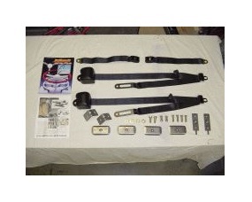
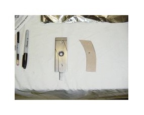
Step 1
These are all the parts included with
the Juliano's seat belt kit. Take some
time to familiarize yourself with the
parts as well as the instructions.
|
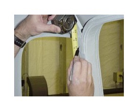 ![]()
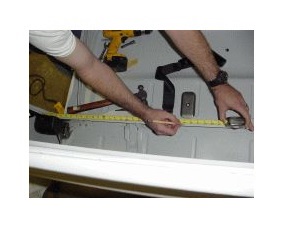
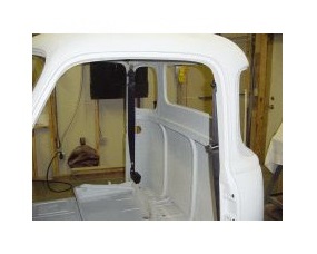
Step 2
Measure up from the floor to locate
the shoulder point. This location can
vary do to seat high and passenger
size so be sure to factor this in.
|
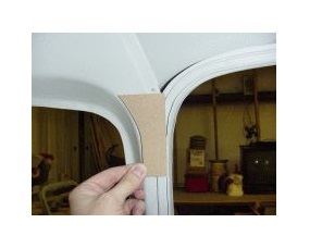 ![]()
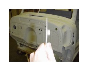
Step 3
Make up a template for the area
as shown that will fit down behind
the sheet metal.
|
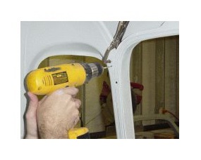 ![]()
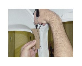
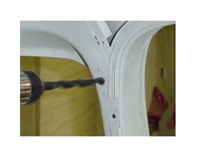
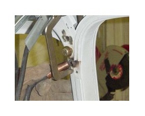
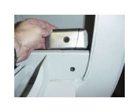
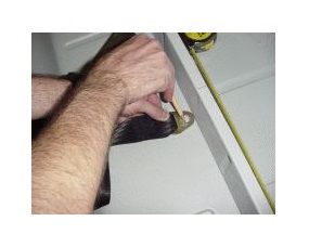
Step 4
Clamp the template behind the
sheet metal and drill an 1/8" hole
at your shoulder point mark, being sure
to drill through the metal and template.
|
Step 5
Align the holes on your template
and fine tune it to clear any
interior panel screws or other
obstructions.
|
Step 6
Trace your template onto the
included B-pillar bracket, being
sure to align the hole with the
threaded shoulder bolt hole.
|
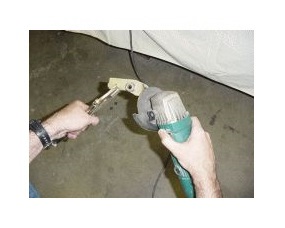
Step 7
Grind or cut the B-pillar
bracket to match your template.
|
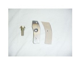
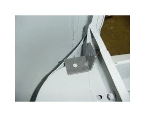
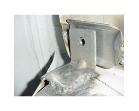
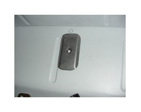
Step 8
B-pillar bracket ready for
installation.
|
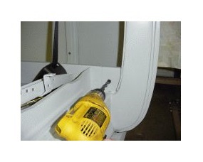
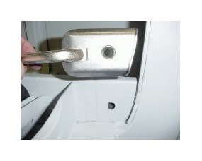
Step 9
Test fit the bracket and be sure
that the pilot holes are aligned.
Now drill the 7/16" hole for the
shoulder bolt.
|
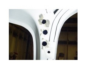
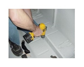
Step 10
Drill two more holes, one above
and one below, to spot weld the
bracket in place.
|
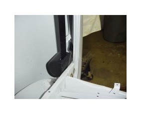
Step 11
You may have to bent the bracket
slightly to match the contour of
the cab.
|
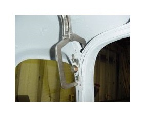
Step 12
Re-install the bracket and use the
shoulder bolt to tighten in place.
You can also use a clamp to hold
pressure on the plate while welding.
|
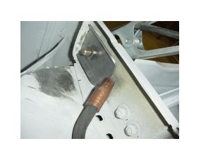
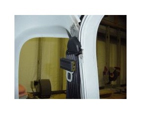
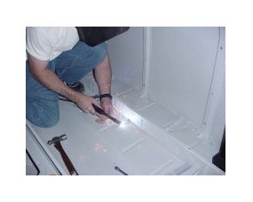
Step 13
Spot weld the bracket in place
using the 2 predrilled holes.
|

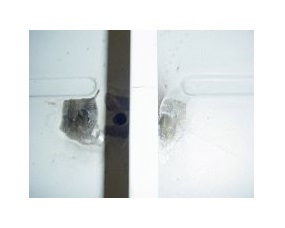
Step 14
Clean up the welds. 120 grit
flapper wheel on a 4" grinder works
well for this.
|
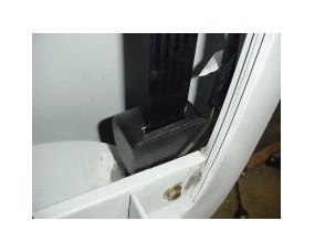
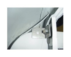
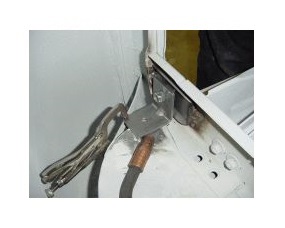
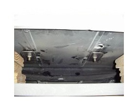
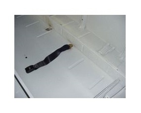
Step 15
Here is the retractor installed.
This location will keep the retractor
mechanism clear of the fuel tank,
filler neck and cab mount.
|
Step 16
Place one of the 90 degree
L-Brackets supplied on the cab
floor behind the seat pedestal as
shown to layout mounting hole.
|
Step 17
Drill the 7/16" mounting hole.
|
Step 18
Next layout one of the included
anchor plates to match the contour
of the cab.
|
Step 19
Trim the plate and mock up to be sure
hole lines up. Adjust as needed.
|
Step 20
Bolt the plate in place using one of
the included bolts. Weld the plate to
the seat pedestal.
|
Step 21
Install the L-Bracket and bolt in place
using one of the lock nuts. The bracket
should sit flat on the floor and the corner
should just touch the small support.
|
Step 22
Weld the L-bracket to the floor and
support beam.
|
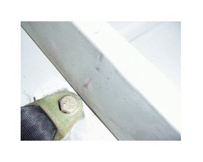
Step 23
Here is the finished mounting plate.
|
Step 24
Mount the retractor by using one of
the 1-1/2" long bolts and washer
through the front and tighten. Install
the retractor and tighten lock nut.
|
Step 25
Install the shoulder point using the
included shoulder bolt.
|
Step 26
Layout the mounting points for the
inboard soft arms. Typical spacing
between the retractor and arm would
be between 15" and 25".
|
Step 27
The holes should be just far enough
in front of the seat pedestal to provide
clearance for the end fitting to clear
the pedestal.
|
Step 28
You may need to adjust the
placement of the plate a little to
provide a flat surface for mounting.
|
Step 29
Drill the 7/16" mounting holes. Also
drill 2 holes to spot weld plates in
place, one just behind the riser and one
just in front of mounting hole.
|
Step 30
Bolt the plates in place under the
truck using supplied bolts.
|
Step 31
Spot weld the 2 plates in place.
|
Step 32
Clean up the welds using a 4"
grinder with 120 grit flap disc.
|
Step 33
Bolt the inboard arms in using supplied
1-1/2" long bolts and flat washers.
|
Step 34
Inboard arm installed.
|
Step 35
Time to enjoy your ride and be safe!
|
|